Mobius Manipulator
This software is still in early development and testing. There are currently known issues and I’m sure some unknown.
Verified Compatible Operating Systems: Windows XP, Windows 7, Windows 8
Software is not yet Mac compatible.
Live Mode: Read settings in from your piece to modify and then write back out.
Selection Box – Lists all available COM ports on your system. This box is trained to look at the most recently added device. If you just plugged your piece in, you will see this number change automatically to your device.
Close – Disconnect piece. Use this before unplugging your piece. If you do not, you may receive an error notification when you try to do anything else in the software.
Connect – Once you have plugged your piece in, clicking connect will connect with the piece and retrieve the LED count of your device. Currently only verification that your piece is connected is by watching for the LED count to change from 160 to your pieces LED count.
Read All – Retrieves all the settings from your piece and loads all the tabs with their data set. Note: POV images may sometimes have an issue here. To avoid snags, read in Image Specs and at least one image before clicking Read All.
File Mode: Load or Save settings for your Mobius Piece. Once settings are read in from your piece, you can save them to a file. Changes can be made and saved to new files to load to your piece at any time. Share files with your friends or keep a collection of settings for different types of events.
Load File: Opens XML file containing Mobius Data
Save File: Only enabled once a file is defined. (Save As or Load previously used). Saves any changes made to the file.
Save File As: Save all settings under a new name. Prompted with Save Window. Enable by clicking New File
New File: Currently only enables Save File As button.
Tabs
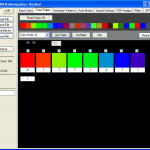
Base Colors: Allows you to modify the 25 colors that are used to create the 46 color pallets.
Color Pallets: Allows you to modify the 46 color pallets used for the Combo pack and POV images. Each pallet consists of up to 8 (of the 25) base colors. Each color can be given a specific length. This gives spacial control to the color layout. In the Combo-Pack, color pallets are masked with the Animation Patterns. In POV-Pack, images are under-laid with the currently selected color pallet.
Animation Patterns: Allows you to modify the 16 patterns that are used in the Combo-Pack. Each pattern represents the on/off state of each LED. (white=on, drk blue=0ff).
Auto Modes: Allows you to setup the Auto Mode sequences. Each sequences consists of 8 to 35 available slots. (Enter 0 for not used). Color pallets are labeled 1-16 for the first 16 solid Base Colors and 17 through 46 for the 30 color pallets . Animation Modes are are 1 through 160, the red mode group is 1-16, the orange mode group is 17-32, the yellow mode group is 33-48, and so on. Changes will be made to animation auto mode sequencing which will allow you to select color group and then 1-16 to make this less confusing.
Speed Settings: Change the speed settings within each group which determines the speed of different mode groups. Currently unlabeled. Group 4 is attached to POV images. The remaining list will be added soon.
POV Images: Editor allows you to specify image dimensions and edit image data. Image Specs must be retrieved before reading in images. Image Specs consist of image rows, image columns, image count, image size, and mirror function. Once image Specs is read in, Image data can then be read. Select the image number from the combo box and click Get Image. The editor window takes a second to load on the first read, give it a few seconds to load, the image selected will then appear in the image editor window. Click on each pixel to turn On or Off. The image will be output through your piece line by line starting at the top of the editor window and reading downward. Once the bottom is reached, the image starts over at the top with no space between (image is butted right up against the next showing of itself). If the Column Count changes after reading specs in from the part, don’t get worried, the piece stores data in groups of 8 pixels, if your image columns are not a factor of 8, the image editor will display them rounded up to the next multiple of 8. (if your image is supposed to be 52 pixels wide, it will read in as 56 wide but the last 4 columns will be blank. While in the editor, you can change it back to 52 and files will save this properly but your piece will return the data as though it is a 56 pixel wide image for any width from 49 to 56)
Filters: Under construction – will allow you to change the order of the mode groups (animations) and assign speed groups to different mode groups.
UPLOAD: Under construction – Currently can set LED count. Will also allow you to set your start modes. Contains form for loading new mode packages or mod files. Also contains password protected direct editor (do not attempt to use unless you are talking with me on the phone at that moment). IF you do sneak past the password protection, be warned you can severely damage (possibly permanently) your piece if you make a mistake here.
Creating a File with a different set of Base Colors
(Create two files containing only Base Color information)
In Live Mode, click Connect to connect to your piece.
In the Base tab, click Read IN Colors. The Base Colors tab will be loaded with 25 colored squares which represent the 25 base colors your piece currently uses.
Click the File button in the upper left of the program.
Click New File, then click Save File As. Type in a name for the file and hit enter. This saves an XML File with only your 25 base colors.
Now modify the 25 colors (or just a few) by clicking on the color box and changing the value of each component with the editor. Once you are happy with the change to a color, click Set and select another square. Once you have made all desired changes to the colors, move on to the next step.
Click on Save File As. Enter a new name for the file and hit enter. This saves a new XML File with the modified base colors. You now have two files with two different sets of base colors.
Writing a File To your Piece
Open the Mobius Manipulator software, in the File Mode, click Load File and select the desired XML file. Only the data present in the file will be loaded to the corresponding tabs.
Click on the LIVE button to switch to Live Mode. Click Connect and watch for the LED count to change. If the LED Count remains at 160. Try plugging your piece in again.
Go to the tab containing the data just read in (will still be there even though you changed to Live Mode). Click the Write or Set button for the data you want to write.
No news is good news, if the write happens without alarm or notification then the data should be programmed to your piece. (Piece must already be connected)
This same exact thing can be done with the data in all the tabs that you see, Including the POV images. Any data that is read in or loaded will be saved to the file when you click Save File or Save File As. To save ALL your settings, read in all the settings in the Live Mode, then switch to the File Mode and click Save File As.